TMAT/Q: working prototype of the first ever headlight switch for quill stems

It’s been over five years since we introduced the TMAT stem switch for threadless stems. I’ve had a lot of requests for a version that could work with traditional quill stems, but that has seemed impossible to achieve. Until now.

The TMAT/Q takes the same basic operational concept of the TMAT and reconfigures things to work with quill stems. That basic concept is the reed switch, which is controlled by the presence or absence of a magnetic field. The original TMAT works on this principle: when you turn the cap, you rotate a hidden magnet and when that magnet approaches the tiny reed switch embedded inside the switch body, the circuit closes and the lights come on. For the TMAT/Q, we rearranged things such that the quill stem itself becomes the central scaffold for the switch components.

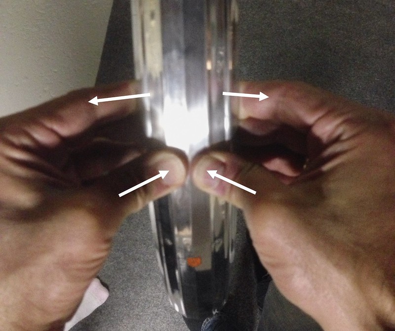
The concept centers on this basic configuration: the reed switch component of the switch is inside the quill stem, while a magnet ring rotates around the outside of the stem, like a headset spacer. The distance between the magnet and the reed switch narrows to less than 1cm as the magnet rotates around the stem, enough for the magnetic field of the powerful neodymium magnet to close the reed contacts.

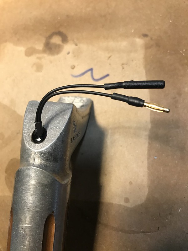
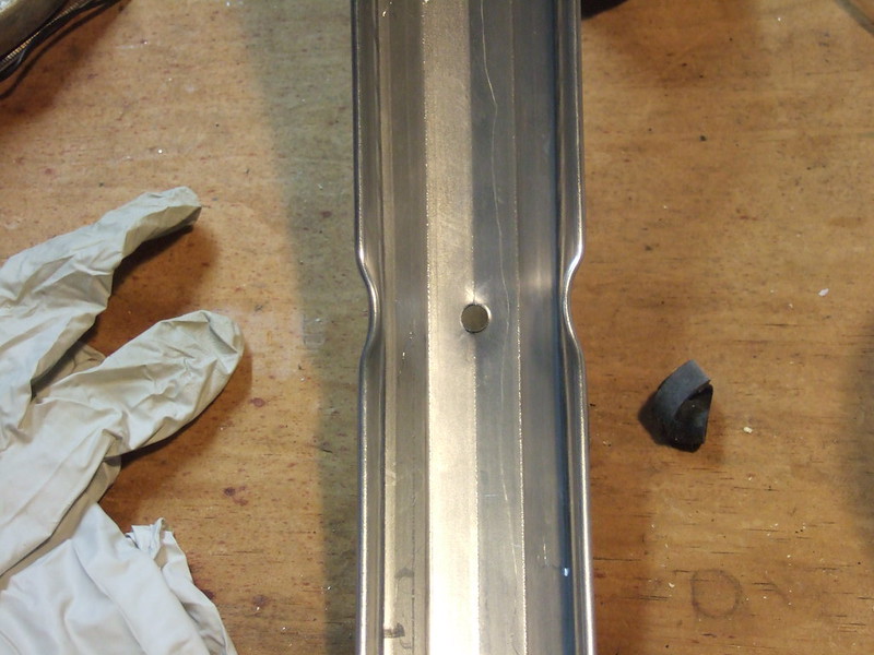
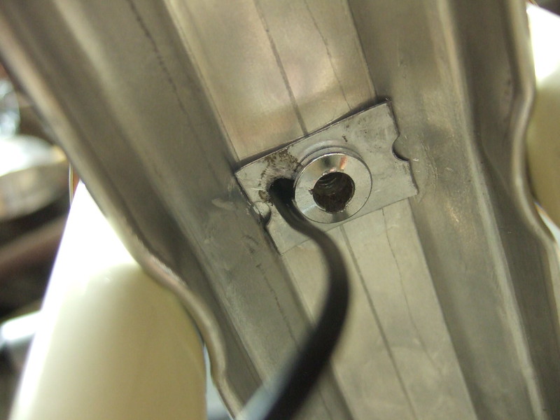
To achieve this, I first created a 3D printed sleeve that slides inside the hollow quill, with a central bore for the M8 stem bolt to pass through. The sleeve contains a pocket for the tiny reed switch. The wires run down to the bottom of the quill, and exit through the expansion wedge via a small hole drilled for this purpose.

Next, I created a 3D printed magnet ring with a small pocket for the magnet, and placed it on top of the headset stack.

Mechanicallly, this setup couldn’t be simpler. Just one moving part: the magnet ring. And it worked!

The next step was to design in travel limits, giving the ring a 1/4 turn range, like the existing TMAT switch. To do this, Tom devised a three-piece ensemble of parts to fit together as a unit around the stem. The first piece is a flanged sleeve which fits around the stem. The second piece is the magnet ring, with a locating pin set through the side, protruding by less than 1mm into the central bore where the stem and sleeve pass through. The ring rotates around the flanged sleeve, and the locating pin travels with the ring along a slotted path in the flanged sleeve. The slot spans 1/4 the circumference of the sleeve. That’s the travel limit mechanism. The third piece is the locking collar, which is just another ring placed beneath the magnet ring. It contains two small M3 set screws, and locks the flanged sleeve to the stem, preventing rotation. This way, the locking collar and flanged sleeve are fixed in position on the stem and hold the magnet ring vertically captive, while the magnet ring rotates freely along a 1/4 turn path around the stem.

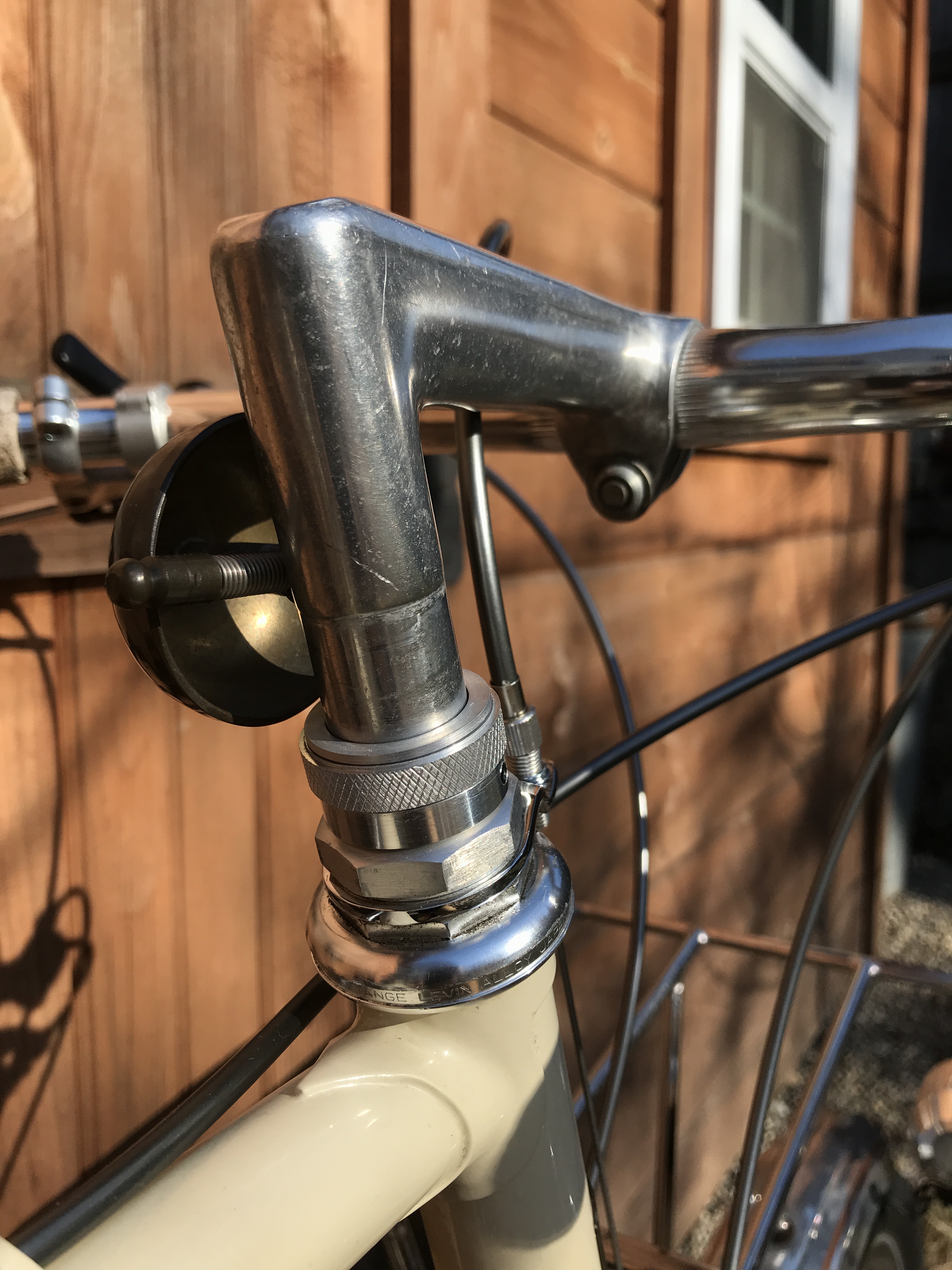
This is the fully assembled package, which is just 32mm in diameter at its widest (the knurled ring surface), and 15mm tall. It takes up no more space than three 5cm headset spacers.

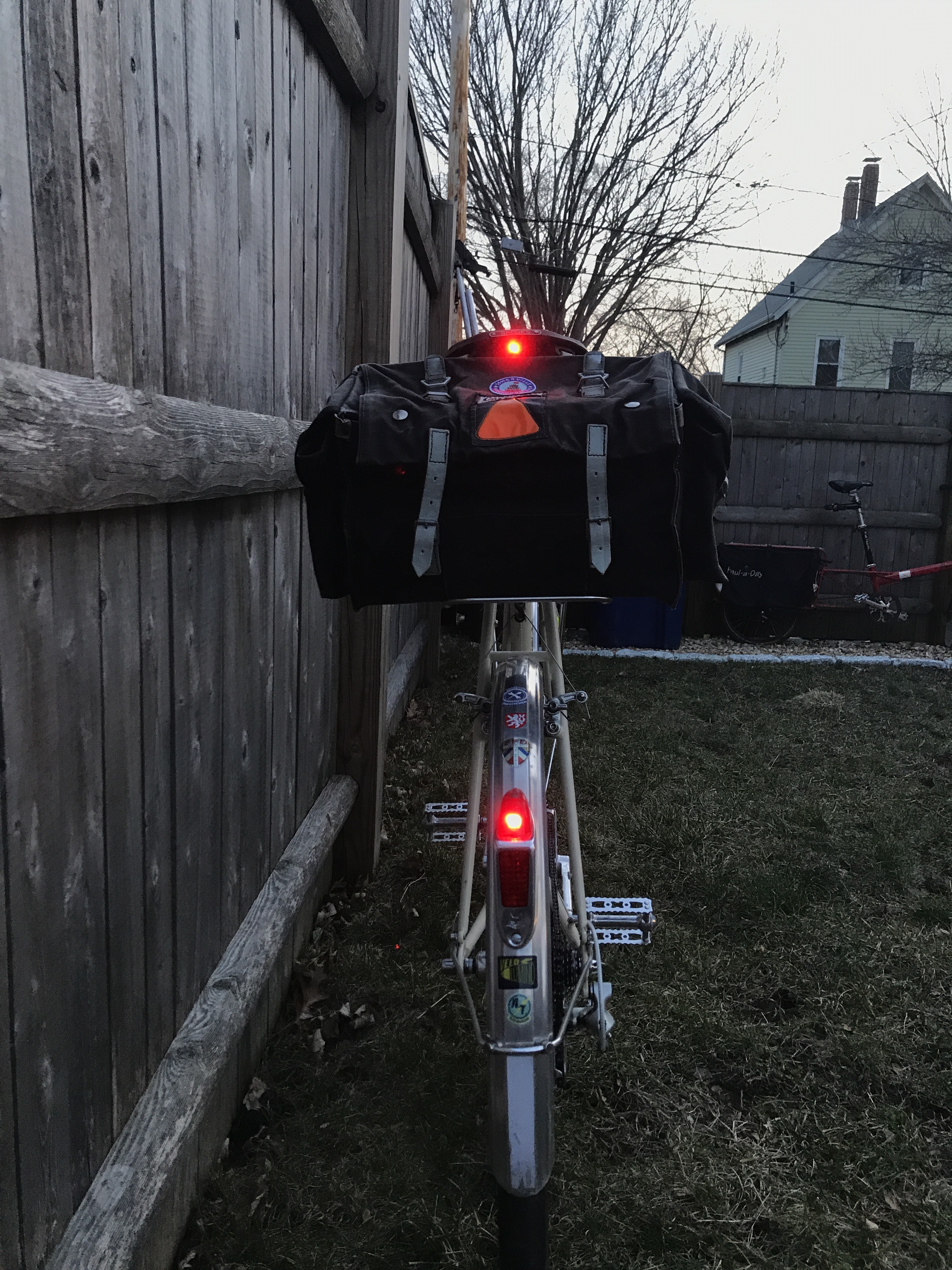
The switch is currently being put to the test on my daily commuter, powering the usual complement of dynamo lights. As is, the switch functions 100%, but it lacks the tactile engagement engineered into the original TMAT, which uses a ball bearing and notched detents at its travel limits to create a very distinct and satisfying positive engagement in the on and off positions. Unfortunately, to keep the compact form factor of the TMAT/Q, we will have to forego the fancy tactile features, but we’re working on a few possibilities for a “soft detent” system, perhaps with magnets. Once we have that detail ironed out, and the prototype has been proven in real riding, we’ll offer it as a custom build option: you’ll send us your quill stem, and we’ll install the switch and return the stem with assembled switch to you.

Now for the caveat: the TMAT/Q won’t work with steel stems. The ferrous quill wall separating the reed switch from the magnet will create a barrier for the magnetic field. So, the TMAT/Q will only work with aluminum alloy stems.

New addition to the Velo Lumino program: The AT Saddlelite taillight mount

I’ve been drawn to taillights for many years, which is one of the reasons I started Velo Lumino, on a whim. I wanted a dynamo-driven taillight (among other things) for my bike, with a particular look that did not exist.

Since then, I’ve continued to be fascinated by taillights. One particular application of them that I’ve been admiring for awhile is the custom work by Mitch Pryor of MAP Bicycles (sadly defunct, fallen victim to the 2018 California fires) and Brian Chapman of Chapman Cycles in mounting small taillights to the saddle. Both these builders have custom-mounted a tiny B&M taillight (or its more high-brow fraternal twin, the SON Rear Light) to the saddle. I love these lights for their tiny size and light weight. They are also inexpensive, at less than $30 (the more upscale SON Rear Light has the same lens and circuitry, but packaged in a bespoke CNC milled and anodized alloy shell, and is heavier and costs three times as much). These lights, and also the Supernova E3 2 taillight, are made for mounting to rear racks via standard 50mm bolt spacing. I bought the tiny B&M simply because I like the look of them (that sounds silly and a little bit on-the-spectrum, I get it), even though I knew I wouldn’t be using it since my bikes were already well-equipped, taillight-wise. Holding it in my hands and marveling at its diminutive size and near weightlessness got me thinking… this is such a cool light… could I design a widget that would allow one to mount this little gem (or any of the other similar 50mm spaced tiny taillights) to any bike without custom braze-ons or one-off fabrication?

I started with a couple of 3D printed prototypes. Both were centered around the idea of having standard 50mm-spaced mounting holes for the tiny B&M light (it’s full name is the B&M Toplight Line Small), which is the Euro-standard for mounting taillights to rear racks.

I quickly centered on having the mount attach to the saddle rails, since they are the most standardized part of any saddle– I wanted this mount to work on any saddle. And I wanted to be so small that it’s barely noticeable. I wanted it to appear as though it were “one with the light and bike”. My first prototype used two lobes that hook onto the rails, with a set-screw in one lobe to create compression between the rails, to keep the mount secure (since the distance between the rails varies slightly between saddles, and the rails also flex somewhat):

IMG_4408IMG_4410
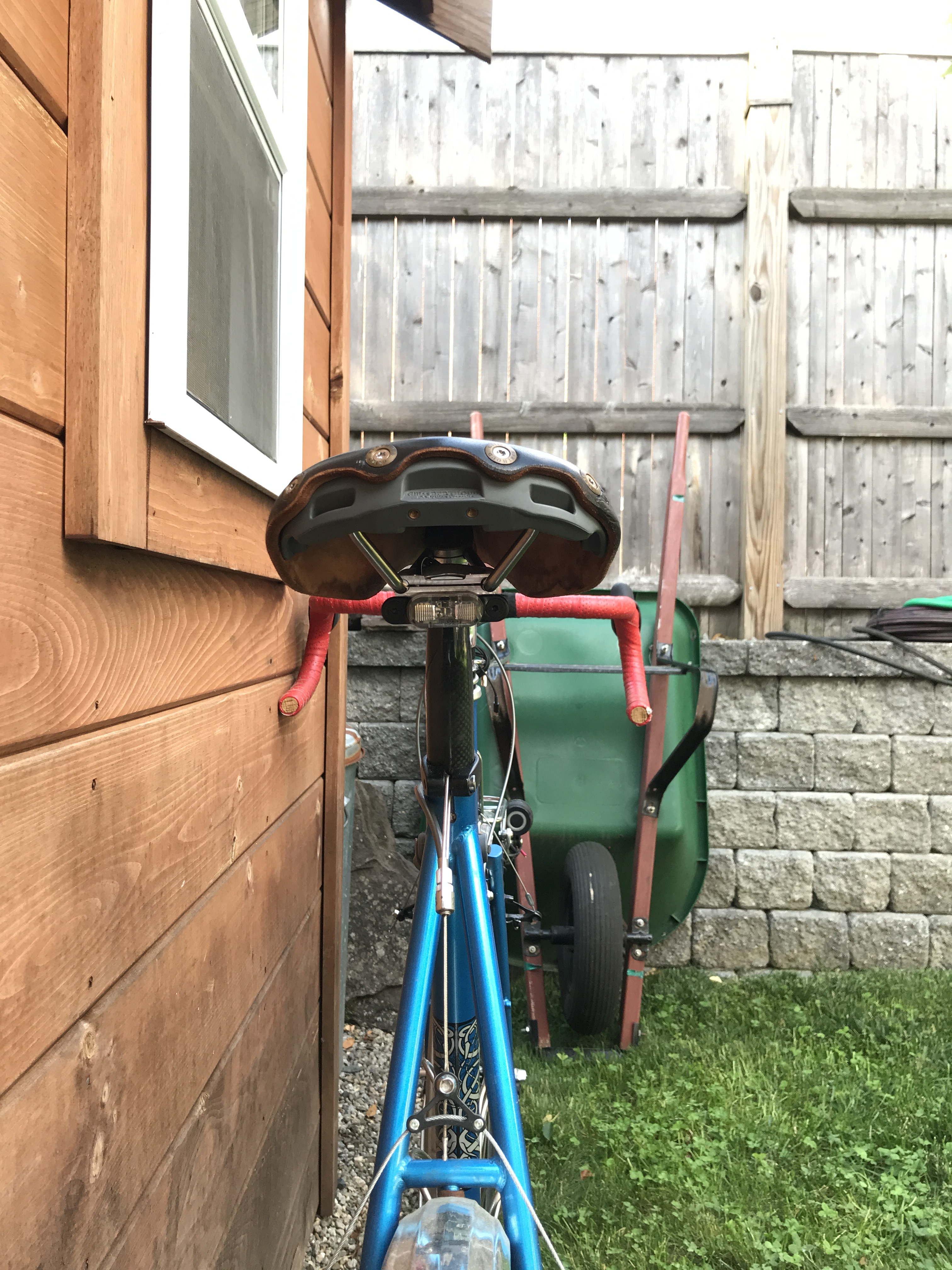
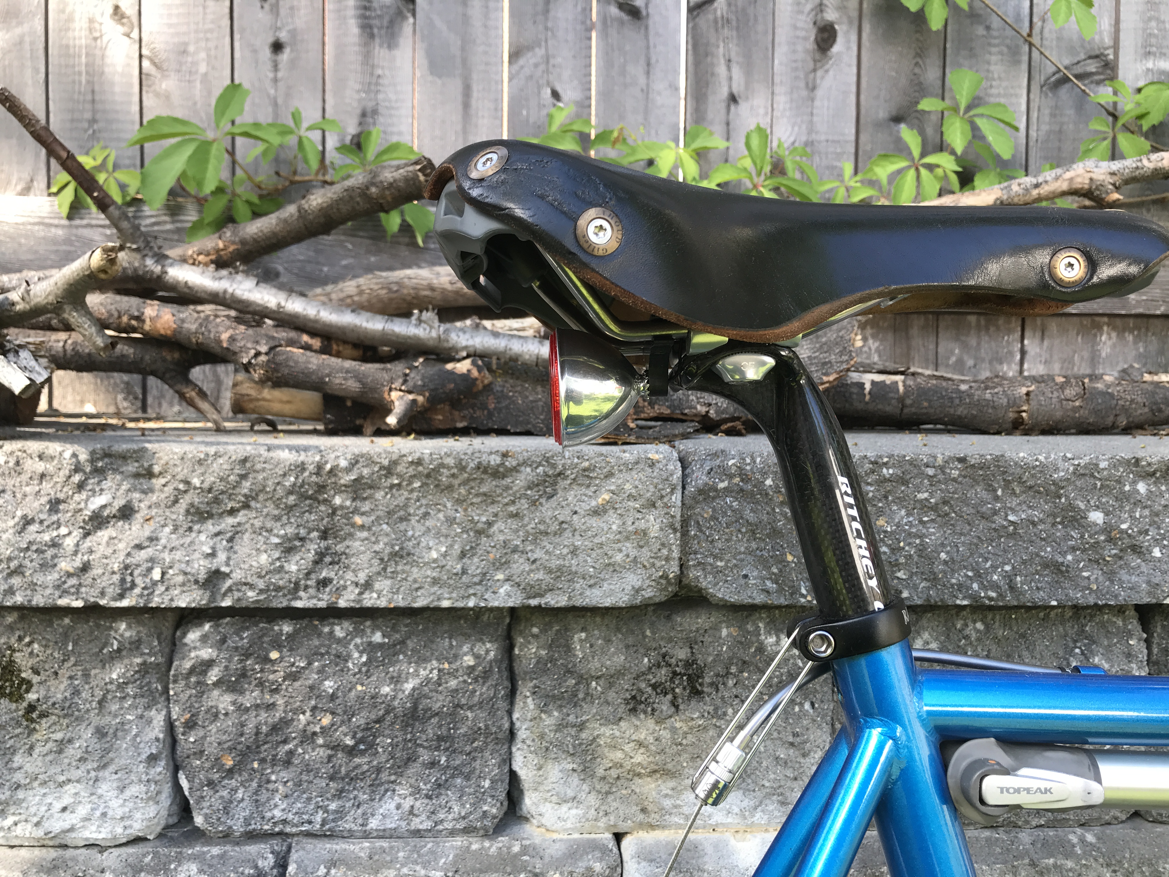
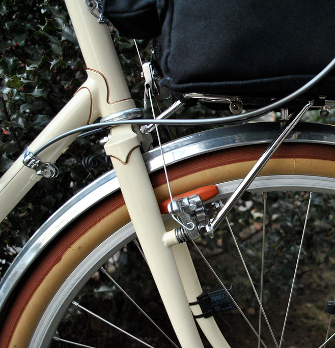
I liked this prototype for its small size and for the way it kept the light very close to the rails– the mount itself is barely visible. Plus, depending on the height of the saddle leather, it also could be mounted upside-down, with the light above the rails, to make it look really stealthy:

IMG_4415

IMG_4413

Definitely headed in the right direction. But I wasn’t happy with the set-screw tightening setup. Even though I never experienced any movement while testing this prototype (I rode my bike with it this way for several weeks on some rough roads), if it were yanked hard enough, it could be ripped from the rails. I wanted it to be rock-solid and theft-proof.

My next prototype was a two-piece system that clamps onto the rails, in the same manner that saddle rails clamp to a seat post, but miniaturized. This worked great–SUPER strong! I ended up making some minor tweaks and took the plunge with the CNC mill work.

So I introduce the Velo Lumino AT Saddlelite (get it?) taillight mount:

IMG_4853

IMG_4851

IMG_4848

IMG_4854

IMG_4855

IMG_4852

The mount is hollowed out in the center to save weight and to allow the B&M wire to be routed through the mount– the wire is invisible this way.

IMG_4858

This little mount is rock-solid, lightweight (13g) and unobtrusive. I have added it to the Velo Lumino webstore, at a price of $42. I am ALSO selling the B&M taillights, in your choice of red or clear lenses (both illuminate red), for $26. You can purchase both together for $62, and save $6. What’s really great about this combo is that it’s a tiny yet bright taillight with standlight capacitor, that mounts to any saddle without modification, and the combo weigh only 30g including all mounting bolts– lighter than any fender taillight I know of.

I chose not to offer the mount in a high-polish finish, unlike my other components. In this case, the mount is designed not to be seen, so I didn’t feel a polished finish was necessary, and it just adds cost. So it’s only offered in its raw milled finish, shown in the photo above. It is a smooth, bright finish, and if you wanted, you could buff it up easily with some metal polish, or paint it black. But really, it’s barely visible when mounted!

Of course, if you want a totally integrated lighting solution, this means internal frame wiring– as is the case with the any integrated dynamo lighting system. In this case, you will want to drill a small hole in the top of your seat post to route the wire into the frame.

What’s next on the horizon? A variation of the Saddlelite that will mount a Velo Lumino seat tube taillight via a single centered M6 threaded hole. The prototyping is already done:

IMG_4859

IMG_4791

IMG_4794

IMG_4792

The seat tube taillight variant of the Saddlelite will be available late summer / early fall… stay tuned!


How to solder 2mm banana plugs

Velo Lumino’s connector of choice has been the 2mm, gold-plated banana plug. Over ten years of experimenting with various connectors from classic spade-type terminals to MOLEX-type terminals, I settled on the 2mm banana plug as my all-time favorite connector for several reasons:

  1. They’re slender and unobtrusive looking anywhere on the bike
  2. The design of the “banana” shaped spring on the male end maximizes the contact area with the interior wall of the female barrel end for very reliable electrical continuity. The contact area is much greater than the contact area between a pair of spade terminals.
  3. The tension of the spring is “just right”: there’s enough friction that the plugs never come loose on their own, yet they’re never difficult to disconnect and there’s little risk of ripping the wire out if the connector is pulled by the wire. There have been many a cyclist who’ve forgotten to remove the spade connectors on a SON hub before pulling the wheel out of the dropouts, only to wind up with torn wires!
  4. Unlike spade terminals, they can withstand hundreds of cycles of connection/disconnection without diminished tension or compromised electrical contact (see this video my videographer shot demonstrating this).
  5. The gold plating means they’re corrosion-proof.

The only downside to the banana plugs is that they cannot be crimped, they must be soldered. Some people don’t own a soldering iron, and even for those who do, soldering these little connectors can still be tricky. My 13 year old videographer shot a video of me demonstrating how to solder a pair of banana connectors and insulate them with shrink tubing. It’s fairly long at almost 12 minutes, and since I’m the type who can ramble on, I had to refrain from a few details in order to keep it under and hour! I will go over some points in finer detail here, using still shots from the video.

Before you get started, you will need a soldering iron. I use a Weller 40-watt iron that comes supplied with a stand and a sponge. You need a damp sponge to wipe the molten solder off the tip frequently, because the longer the molten solder stays on the tip, the more it oxidizes, and oxidized solder won’t wick onto its substrate. For a soldering tip, I prefer a flat screwdriver shape, such as the one that comes with the Weller. You will also need either a heat gun or a high-wattage hair dryer to apply the shrink tubing. You will also need a soldering stand (or jeweler’s stand) to hold the parts to be soldered in place. You can find these all over the internet:

IMG_4235

First, strip just a couple of millimeters of insulation from the wire. Hopefully you’re using Velo Lumino’s premium wire with the super thin cross-linked polymer jacketing. It’s the highest quality wire I’ve found, and it snakes very well through tight passages such as in the fender’s rolled edge and through frame tubes. Twist the strands several times to create a tight bundle and prevent stray wires from splaying outward during soldering.

Clip the wire into the alligator clip and wick some solder into the exposed wire. This is called “tinning” the wire. Wires with pre-tinned ends fuse more quickly with the pre-tinned banana plugs when re-melted. You only want to wick a tiny amount, don’t go overboard. I’ll explain why later. The best way to do this is to touch the iron tip to the wire to pre-heat it (just a second or two), and while doing so, touch the solder to it. It should melt and wick almost instantly.

IMG_4237

As soon as it’s molten and wicked, remove the iron.

Next, tin the banana plug. I’ll start with the female end. When you look closely at the female banana plug, you’ll notice that one end has a stop about 2mm into the barrel. That’s the “cup” end and it’s the end that accepts the solder. You want to fill the cup with solder about 1/2 to all the way full. This is a little trickier than tinning bare wire. If you use the same approach as tinning a bare wire, you will end up with an air bubble trapped in the cup and a little ball of solder on top, or you’ll end up with solder wicking down the outside of the barrel.

Instead, insert the cold solder into the cup FIRST, THEN apply heat to the outside of the cup until the solder starts to melt and fill the cup:

IMG_4230

I love this shot because it illustrates a few things. First, note the flat end of the iron tip contacting the side of the barrel. This maximizes heat transfer, which would be less efficient if not impossible with a pencil-tip. Second, note the barrel isn’t placed all the way into the alligator clip. You want at least half of it sticking out the end to minimize heat transfer to the clip. If the clip acts as a heat sink (this is a phenomenon well known by frame builders), you might not conduct enough heat to melt the solder. Lastly, you can see the solder already beginning to melt and fill the cup. Now’s a good time to pull out the cold solder and remove the heat. You only need the cup partially filled, but all the way is okay, too.

Next, get the tinned wire ready, and reapply heat to the solder cup.

IMG_4239

As soon as it’s molten again, press the wire into the cup. As soon as it’s in, remove the heat and hold the wire steady until the solder solidifies. This should take just a few seconds. (Note the photo below is not of the same female plug shown above, but the male plug, but the process is identical):

IMG_4243

The soldering is done. Now apply the shrink tubing. The 6″ long shrink tubing sold by Velo Lumino is the optimal diameter for the 2mm plugs and is enough for four pair of banana plugs. Cut a 2cm piece for the female end, and a 1cm piece for the male end. This leaves enough shrink tubing to extend beyond the solder cup and a few additional millimeters along the wire. Getting back to my comment earlier about not applying too much solder when tinning the wire: soldered wire is brittle and will snap if bent back and forth. The farther the solder wicks into the wire (a function of time and amount of solder applied), the longer a section of wire will be brittle. This is why you only apply a tiny amount when tinning, and it’s also why you remove the heat as soon as the tinned wire is inserted into the cup of molten solder. Having the shrunken tubing continue over the wire past the solder junction is essential for providing rigidity to the soldered area to prevent bending.

For the female plug, hold the 2cm long tubing in place with one hand such that it overhangs just slightly (0.5mm, max) off the end:

IMG_4245

While holding it steady, shoot it with the heat gun (or hair dryer), aiming for the end opposite your fingers first (for obvious reason). As soon as the far end shrinks, you can let go and move your fingers further along the wire away from the connector so as not to get burned. (If you don’t hold it in place initially, and just hit it with heat, the blast of air from the heat gun will blow the tubing away from where it should be). Hit the rest of the tubing with the heat gun, rotating the wire to distribute the heat evenly so as to avoid hot spots that might melt it (although, my 1500W heat gun has never melted the shrink tubing). Think roasting marshmallows over a fire.

For the male end, position the 1cm piece of tubing just aft of the barrel spring:

IMG_4247

Hit it the same way with the heat gun, being careful not to burn your fingers!

IMG_4249

All done! (Apologies for the blurry video still).

IMG_4251

You can see plenty more examples of soldered and insulated banana plugs in the Velo Lumino gallery.

A longtail of two taillights

For the past 14 years I’ve been bike commuting to work year-round. I started out with battery operated lights, as dynamo systems hadn’t yet gained popularity and were expensive, and LED technology for lighting was still in its infancy. With the first generation of LED dynamo lights, I upgraded my bikes to dynamo systems. For the past 10 years, my bikes have been equipped with dynamos and they’ve always had a single headlight and a single taillight. I’ve always felt that my lighting has been adequate and it has been a luxury to be able to just hop on my bike and ride, knowing the lights would work. No more frustration over dead batteries. In the years since, I’ve upgraded my lights as newer, more powerful LEDs and superior optics have emerged.

Concurrent with the advancement of dynamo lighting, I’ve seen cycling infrastructure expand dramatically, adding to a sense of safety. Yet lately, local and national traffic fatality trends have been disturbing. Pedestrian and bicycle fatalities involving motor vehicles are on the rise despite expanding cycling infrastructure and despite many communities adopting Vision Zero policies. Sadly, the US is not committing to this concept on the national level. But even as towns and cities across the US (including the one I live in) are embracing Vision Zero and aggressively building cycling infrastructure, fatalities continue.

I’ve twice been the victim of rear-end crashes: once in a car, 30 years ago, and once as a cyclist, 11 years ago (ironically I was injured in the car crash but not in the bike crash). At certain intersections around Boston when I’m waiting to turn left, I still experience fear that I will be rear-ended. I wear a helmet mirror and have become very dependent on it; I‘m acutely aware of what’s happening behind me, but the fear never goes away entirely.

A few years ago I started supplementing my dynamo lighting with a second, battery taillight, just for some extra visibility. But the same frustrations ensued– I’d arrive home at night and find the battery taillight had died. So last year I asked what would happen if I added a second dynamo taillight to my bikes? Would it increase the drag? Would it cause the other lights to dim as the dynamo maxes out its output?

The answer was no! A standard dynamo setup uses a 6V AC generator nominally producing 3W of power. A dynamo-driven headlight draws 2.4W while a taillight draws 0.6W. Adding a second dynamo taillight will increase the total draw to 3.4W, an increase of about 20%. In reality, if the dynamo is topping out at 3W and can’t produce any more, it just means that each light will receive slightly less power, and most dynamos will output more than 3W at higher speeds, so there should be enough reserves for that added 20% load. I haven’t noticed any decrease in brightness at all. As a side note: Dynamos for small-wheeled bikes produce the same 3W of power but require higher RPMs to achieve it, which has the benefit of cuasing less drag compared to a standard output dynamo, but lights driven by these lower drag dynamos tend to flicker until slightly higher speeds if used on bikes with large wheels. This is a common drag-saving trick of randonneurs. Dynamos like the Schmidt SONdelux and Shutter Precision SV- and SD-series fall into this category, and are a common choice for 650B and even 700C bikes designed to be ridden for brevets where you’re not crawling around at low speed. Even these lower-drag dynamos are capable of driving two taillights. I know because both of my commuter bikes have these lower drag dynamos: one has 650B wheels and the other has 20″ wheels, with no significant drag or flicker issues. The 650B bike will have some flicker if I’m huffing up a steep hill at about 6mph, whereas with just one taillight the flicker would cease at about 4-5mph.

Here are my recently updated commuters:

This is my winter commuter, a Bike Friday Haul-a-Day longtail cargo bike (which I also use throughout the year for hauling stuff but not for general commuting). This bike has a B&M Secula on the fender, and a Schmidt SON seat post taillight:

IMG_3904

This bike doesn’t have any internal wiring, it’s all exposed, but the external wiring has held up well over the five years it’s been in service despite being stored outside year-round (the bike is too long to get into my basement or my shed).

And this is my three-seasons commuter, a 650B-converted 1980s Japanese touring bike, with a  vintage Soubitez fender taillight retrofitted with a B&M Seculite LED circuit, and another B&M LED (just the LED+circuit board coated in epoxy, barely noticeable) mounted under the saddle, peeking out between the saddle and the saddlebag:

IMG_3915

IMG_3916

49051722363_ab6cdced7b_c

This bike has the wiring integrated inside the frame, and to maintain that integration when adding the under-saddle taillight, I ran a wire up the seat tube and out of the seat post. I drilled a hole at the top of the seat post for the wire to exit, and of course I used my favorite banana plug connectors at multiple points along the way so lights and other components can be swapped out in the future without having to rip out any wiring.

49048727963_91602ea2ee_c

49049228696_1d0b849266_c

After living with dual taillights on my commuters for the better part of a year, I don’t think I’ll ever go back to a single taillight!

And I’ll leave you with a little taillight limerick I coined some years back:

Stopping at stoplights without exception
Waiting for dusk’s inception
On my saddle I sit
My light always lit
Keeping me seen in the intersection

Using a recessed brake bolt or seat post binder for 650B conversion fender attachment at the crown

A common challenge when doing 650B conversions of 700C (or worse, 27″) frames is getting acceptable fender spacing. For these frames, the fork legs are longer than ideal, and the chainstay and brake bridges are farther away from the axle than is ideal for mounting a fender.

The bridges can be dealt with by using spacers. Not ideal, but they do the job. A bigger challenge is how to attach the front fender to the fork crown. The fender will usually require a large gap at the crown, taken up by spacers, looking something like this (this is an extreme example, going from 27″ to 650B):

5411771107_8cc694e743_c

Most fenders attach to the crown using a daruma bolt. This presents a problem because most Daruma bolts don’t extend far enough to reach the fender through the massive stack of washers like shown above. There exists a very simple solution to this problem! Just extend the Daruma bolt! Instead of using a nut threaded onto the Daruma, a standard M6 threaded recessed brake bolt or female seat post binder bolt will thread onto the Daruma and extend it far enough to reach through that honkin’ stack o’ washers to the fender. Compare the usable daruma length with a standard nut with that of a seat post binder (or brake bolt, take your pick):

5402782717_2e2fce3c5a_c

Alternatively, you can go to your local hardware store or go online and pick up an M6 “stand off” adapter, in either female-female, or female-male, which looks like this:

f8066663-01

However, these might set you back a few bucks more than it’s worth for you to sift through your parts bin, or even the used parts bin of your LBS, where you might pick up a brake bolt or seat post binder for a buck or two… or maybe even free.

And as an aside, don’t worry about that big gap between the fender and the crown in the first pic. Once the bike is built up, you won’t even notice it:

6792849869_8ce93837e8_b


How to install metal fenders, Part IV: installing the stays

In Part I, I described how to “massage” fenders into the proper arc radius. Part II covered stress-relieving the fender before mounting. In Part III, I went over dimpling the fenders. In this final part in the series, I will go over the final step: installing the stays.

Most metal fenders (Velo Orange, Honjo) come with U-shaped stays, with the radius of the “U” curve proportional to the width of the fender. Some fenders are supplied with metal brackets to secure the stay to the fender, but most come with a type of draw bolt that looks like a miniature daruma bolt. VO fenders are pre-drilled for two draw bolts, whereas Honjos require the installer to drill them. For Honjos, the choice of how high or low on the fender to drill the holes is a personal choice. I like to drill them lower than VO does, but it’s really just an aesthetic preference. I will describe installing stays with draw bolts since those are the most common.

The draw bolt secures the fender by compression of the stay in the eye of the bolt. This is achieved by a cupped washer, which exerts a sheer force on the stay when the nut is tightened, locking the stay in position. The stays are then fastened to the frame at the dropout eyelets with R-clamps.

The key to successful stay installation is to have the fender already mounted to the frame, properly radiused and stress-relieved. The stays are only securing things in place, not changing the fit. The fender below has been installed according to Part I and II and is ready to have its stay installed as the final step:

IMG_3925
Fender ready to have its stay installed.

Slide the two draw bolts onto the stay and position them around the U. Add the two cupped washers and insert the draw bolt threads into the fender.  While holding the two draw bolts on the fender, thread the washers and nuts from the underside the fender. Thread the nuts most of the way but don’t tighten them. This is critical. You want to be able to slide the stay left and right in the draw bolts until the stay is aligned laterally with the dropouts. The stay should stick out to the left and right of the dropouts by default, and extend past them. When the stay is in alignment and the lateral gap between the stay and left and right dropout eyelets is equal, start tightening the draw bolt nuts. Do this slowly. As you tighten one draw bolt, it will slightly change the lateral alignment. I usually do 1/8 to 1/4 turn of one nut, then the same with the other, alternating. With each turn, keep the lateral alignment in check. This is crucial. Don’t correct the alignment by bending; loosen the nuts and re-align. It might take a bit of back and forth to get it right. Don’t overtighten the nuts, you should be able to rotate the stay up or down, and get it in the proper vertical position for the R-clips. You can mount the R-clips with the bolt hole facing up or down, but the stay should be rotated appropriately. They should look like this:

IMG_3931
Fender stay with its draw bolts tightened. The ends are just hanging in the air.

Next, bend the stay ends so that they are parallel with the dropout. By default, they are not parallel, they point outward, and if you tighten the R-clip at this point, it will apply a bending stress along the stay. I don’t get very precise with bend placement, I just grab the stay with two hands, one mid-way along the stay and the other at the end, and I create a slight bend a few inches (4-6″, doesn’t matter too much) from the end, in toward the dropout. This might cause the stay to push against the dropout, that’s fine for now. Do the same with the other side. If you bend too much, the stay will be non-parallel with the dropout, but in the other direction, pointing in. Just bend it back. The front stay gets bent only very slightly, since the hub diameter is 100mm, compared to the rear stay which has to get bent a little more because of the wider dropout spacing.

Once you have both sides of the stay parallel with the dropouts, assess how tightly they’re pressing against the dropouts. You want them to just float next to the dropout, or touch it lightly but without any pressure. You can relieve this by gently bending the entire stay outward, with one hand on each side of the stay, bending the left and right sides equally. If you go too far, just bend them back in. In the end, this is what you are aiming for:

IMG_3935
Front fender stay bent to be parallel with dropout.

IMG_3947
Rear fender stay parallel with dropout.

I cheated and got a little ahead here: these photos show the stays trimmed down after test-fitting the R-clips and marking where to cut the excess stay.

At this point, you’re ready to install the R-clips, pop the wheel in, and check the fender line. In addition to the fender line, also check the lateral alignment with the wheel. If it’s not centered, a common (but wrong) trick is to slide the stays inside the R-clips to skew the fender left or right. A better way is to remove the R-clips and the wheel, and physically skew the fender left or right by hand. Sometimes you have to skew it quite a bit for any change to “stick”. You can twist the fender pretty far before you begin to cause permanent damage. Pop the wheel in again and check.

IMG_3924
Fender laterally aligned before tightening the R-clips.

Once it’s good, install the R-clips again, and mark where to cut off the excess stay. I like to leave about 1-2mm of stay sticking out the front of the R-clip, but depending on the placement of the eyelet, this may interfere with the axle skewer. I cut the excess stay off with a dremel cutoff wheel, and then use a de-burring wheel to clean up the edges, and finally a carbon steel brush wheel to polish it up (if the stays are polished, as VO stays are; Honjo stays are matte, so I don’t use the brush wheel after de-burring). I do this with the fenders and stay installed, I just pull the stay away from the dropout and take care not to let the dremel slip and mar the frame. The stay just snaps back into place, it takes a lot of pulling to change the alignment.

IMG_3950
Stay trimmed down. In this case, all the way to the R-clip to avoid interference with QR skewer.

Reinstall the R-clips and tighten. Your fenders are done!

How to install metal fenders, Part III: dimpling the fenders

In Part I, I described how to “massage” fenders to achieve the proper arc radius. Part II covered stress-relieving the fender before mounting. In this part, I will go over dimpling the fenders in order to fit through narrowly spaced fork legs or chain stays that create “pinch points” for the fenders.

Sometimes it becomes necessary to squeeze the fenders to fit through tight passages like fork blades or seat stays. Ideally, a frame is designed around fenders of a given size, making dimpling unnecessary, but sometimes there’s no way around it. Sometimes larger tires are fitted to frames not designed for them, and that may also necessitate choosing wider fenders than the frame was designed for. Also, bikes with fastback-style seat stays generally have less available width at the brake bridge, creating a pinch point for fenders that might not be the case elsewhere on the frame.

Some people choose to trim away the sides of the fender using tin snips or a cutting wheel to make clearance. This solves the problem of fit, but can introduce stress risers by structurally weakening the fenders at the cut points by removing the fender’s rolled edge. Dimpling is the better solution, and it can be done cleanly, so cleanly that you often don’t notice it.

To dimple a fender, you want to make a form with a smooth-radiused channel running through it. I made my own out of a scrap of wood:

5396998480_003a2d3cca_c

I created it from a block of wood by drilling a 7/8″ hole at an angle, then I made a miter cut through the block midway across the drilled hole:

5396999602_eb56d8633f_c

An ideal setup would be to have multiple forms made with different diameter channels optimized for different parts of the frame: fork blades generally require wider diameter dimples, while seat stays require narrow diameter dimples. I am not that sophisticated with my DIY jigs, so I use the same one for all dimpling. I’ll explain below how I compensate for the lack of differently sized jigs.

You will also need a wooden dowel of similar diameter to the channel in your wood form.

With your properly radiused and stress-relieved fender, mark where you want to create the dimple. If it’s around a fork leg, force the fender into place (it will get pinched but not permanently), then mark the fender with a sharpie marker in front and behind the fork leg. (Use mineral spirits to dissolve the “permanent” ink later on…). Hammer the dowel against the fender to create a dimple between the two marks. The cavity in the supporting form will prevent the dimple from becoming too deep and will help create a smooth radiused shape to the dimple.

IMG_4095

Here’s a schematic illustrating how to position the fender on the form. The illustration is a side view:

5538370819_1d0e412624

Next, use the same (or similar) diameter dowel as the hole you drilled into the wooden form, and hammer the dowel against the edge of the fender lightly. I use a rubber mallet:

IMG_4096

As mentioned above, ideally you would have both narrow and wide, shallow and deep channels with corresponding diameter dowels to create custom sized dimples. I don’t have that level of sophistication, so when I tap the dowel, I tap gently at first, and examine the size of the dimple. If it’s not enough, I re-position the fender on the form and tap harder. It’s not a perfect science.

The fender should come out looking something like this. My one and only jig had been made for this particular dimple size, to wrap around the fork blades on a bike clearly not originally made for fenders this wide.

5403380340_4bbc91d442_c

5403377004_9fcebe5c6d_c

And after installing. This fender was dimpled to fit between narrow fork legs (the wire was part of the integrated dynamo wiring that was part of the build for this bike).

5412383722_b371ca30aa_c

The rear fender for this mixte frame had to be dimpled at the seat stays, which didn’t have quite the clearance for the chosen fenders. The dimples were made on the same jig as used for the example above, but I tapped the dowel gently for a shallower dimple. You can barely make it out:

5639276526_2763b0479e_c

In Part IV, the final in the series on metal fender installation, I’ll cover the final step: installing the fender stays.

How to install metal fenders, Part II: stress-relieving before mounting

In Part I, I described how to perfect the fender line to your bike’s tire arc radius. Here in Part II, I will discuss the concept of stress-relieving, why it’s important, and how to mount your fenders to minimize stress risers.

Oftentimes, people will install fenders by brute force. They will drill holes corresponding to where the frame’s mounting bosses are, but then they’ll bend and adjust the stays to attempt to force the fender into a satisfactory alignment. Sometimes the outcome might look well enough, but the fender is under stress. You can tell if a fender is stressed by simply removing one bolt. It might be a bolt attached to a mounting boss, or a stay bolt fastened to the dropout eyelet. As soon as you loosen the bolt, the fender shifts (sometimes violently) out of alignment. It’s trying to revert to its resting state. The problem with stressed fenders is that the stress becomes localized to very focused points, concentrating the stress. These foci of stress are known as stress risers. Over time and ongoing vibration from regular riding, the metal fatigues at the stress risers and fails. The metal eventually develops a cracks. Catastrophic things can happen when a fender fails at speed. Thus, we need to minimize stress risers when installing fenders. No fender will ever be free of stress, as vibrations and flex of the bike translate to the fender, but stress-relieving essentially means spreading the stress over as broad an area as possible, and not concentrating it into stress risers. This is accomplished in several ways.

First, make sure that none of the fender attachment points to the bike pull the fender away from its resting state, but rather “lock” the fender in that state. You’ve already “massaged” the fender into a perfect arc radius for your bike, leaving 1-2mm of space between the fender and its mounting bosses. You’ve created a new resting state for the fender. Now you need to maintain that resting state with each and every attachment point to the bike. Ideally, the bike builder has thought about this and carefully placed multiple mounting bosses to be concentric with the wheel. So, theoretically you should be able to just drill holes in the fender corresponding to each mounting point, bolt the fender in, and not introduce any stress into the fender or distort your perfect fender arc line. But it’s not always that easy. Sometimes the mounting bosses aren’t perfectly concentric with the wheel and you need to compensate with spacers.

Let’s talk about mounting points. I like to divide them into two types: hard, and soft. Hard mounting points are those that are built into the bike or rack, and therefore are rigid. The include the fender bosses on the brake bridge, chainstay bridge, fork crown, and on the rack, if a rack is part of your build. Soft mounting points are the eyelets at the dropouts, and the attachment points between the stay and the fender. These are “soft” because they do not contact the fender directly; the stays bolt to them and bridge the fender to the rigid frame. The stays help distribute stresses acting on the fender as the bike is in motion and generating twist and vibrations. The hard mounting points are the major sources of stress because they won’t move as the fender flexes from riding. Hard and soft mounts get treated a little bit differently. Hard mounts should have a rubber or leather washer placed between the mount and the fender (hence the 1-2mm space between the fender and the mounting boss when doing the mock up). This helps distribute the stress at the mounting point. The soft mounting points like at the stays or eyelets don’t need a soft washer.

Let’s start with the front fender. There will be a minimum of one mounting hard mounting point: beneath the crown. There may be a second hard mounting point built into a front rack if your builder has built one for your bike, or if you’ve bought a production rack that has a built-in fender mount. But let’s focus on the crown mount first, because this one’s the most important, and also a common major stress point. The reason is because the crown mount (if the bike has one) is not tangential to the fender as the fender passes through the crown. This is due to offset built into the fork. If the fork had zero offset, the crown would be tangential to the fender. Some savvy builders will braze a mount below the crown angled to compensate for the fork’s rake, so the mount will be tangential to the fender. Kudos to those builders, but this is rare. Most likely there is just an M5 threaded boss coaxial with the steerer tube. Or there is no mount at all and you have to use a daruma bolt supplied by VO or Honjo. (Or, you can use the Velo Lumino TM PLugNut). But in all these cases, the bolt attachment will still be parallel with the steerer tube, and not tangential to the fender. If you drill a hole in the fender and mount it to the fork crown, you will create an uneven stress riser because the fender will want to remain tangential to the crown. My solution is simple: create a dimple in the center of the fender where you want to mount it to the crown, such that the dimple allows the fender to have the correct orientation when bolted to the crown. The dimple will be stress-relieved: all the forces between the fender and the crown will be distributed across the area of the dimple.

How do you create the dimple? Drill a 1/4″ hole (6.3mm) in the fender where you want to mount it to the crown. Assemble a DIY press made from some M5 or M6 threaded stock (or a long bolt), pass it through the hole you drilled, get a bunch of fender washers (ha! how apropos!) available at any hardware store and stack a few on either side of the fender. Thread a bolt on either end and sandwich the fender tightly. Keep tightening the sandwich until the compression of the assembly fully flattens the arched fender into a flat circle the same size as the fender washers. Next, apply force to the tightened press toward the front of the fender, so that you are now forcing the front half of that flattened circle you created to cavitate down below the surface of the fender. Here’s a schematic:

8227046913_f2b426a428_o

And here’s how the final outcome should look. This was done on a Honjo hammered fender, and we’re looking at the underside. When the fender is installed, the upper part of the fender in the photo will be forward of the crown.

14765823254_b9bd85e12d_c
Pressed indentation in the shape of a fender washer using a DIY press.

dimple

Notice how the flattened circle is cavitated at the top but not at the bottom. Now when the fender is bolted tightly to the fork crown, the fender should assume a near perfect orientation, concentric with the front wheel, without any additional mounting points supporting the fender. When mounting to the crown, which is a “hard” mounting point, at least one rubber fender washer should be used. If the position isn’t perfect, you can manually finesse it by grasping the front and rear of the fender while bolted tightly to the crown and force it one way or the other. Essentially you can use the fork crown as the DIY press for the final finessing.

Here’s a fender mounted only at the fork crown. The stay isn’t installed:

27414620712_fcefa27813_c
A stress-relieved attachment at the fork crown allows the fender to assume it’s proper alignment without an additional support.

No part of the fender is touching the tire and the concentricity is almost perfect. A little tweak here and there to the pressed crown cavitation and it’s ready to have the stays installed.

For the rear fender, the process is easier, since you don’t have to create a fancy pressed cavitation. All the mounting bosses should be tangential to the wheel. Just take care to make sure the fender is stress-relieved at all the bridge mounting points and include a leather or rubber washer. I like to do the “hanging test” like with the fork crown by bolting the rear fender to just the brake bridge mount since its closest to the top of the fender. Then observe how concentric the fender is with the wheel installed, and adjust as necessary. Then bolt to the chainstay bridge.

A note on chainstay bridges: some older British bikes, and some bikes not designed specifically for fenders, lack a threaded boss at the seatstay bridge. If there’s an unthreaded bore, you can use a bolt and nut. Without a bore, you can wrap a nylon P-clamp around the bridge, and bolt the P-clamp to the fender. Here’s a vintage Jack Taylor with an undrilled chainstay bridge. I used a plasti-dipped metal P-clamp because that’s what I had in my parts bin, but I prefer nylon:

38002164911_680b90f59c_c
A P-clamp can substitute for lack of a mounting boss, or an un-drilled chainstay bridge.

There are two steps left to complete the fender installation: dimpling the sides of the fender for cases where the fender is too wide to clear the chainstays (as was the case with the Jack Taylor above), and installing the fender stays. I’ll cover dimpling next, in Part III, and the stays in Part IV, the final in the fender series.

How to install metal fenders, Part I: achieving a proper arc radius

I do a lot of lighting installations on custom bikes, and one thing I am frequently asked when discussing customers’ needs is if I will install fenders, too. Fenders are one of those components that a lot of folks aren’t comfortable installing. Fenders don’t just bolt on easily the way a stem or seat post do. Firstly, fenders come in various shapes and sizes. Secondly, mounting holes need to be drilled, fender stays trimmed down to size and installed, and some manual shaping is usually required. Lastly the bike on which the fenders are being installed must have mounting bosses thoughtfully placed so as to hold the fender in a proper arc line, concentric with the specified tire size. On custom bikes designed for fenders, care is usually taken by the builder to properly space the mounting bosses to achieve a desired fender arc, given a desired size tire.  The wider the tire on a given size rim, the larger the arc radius. There is no way for a fender to simply “bolt up” and achieve a perfect arc radius without careful manipulation.  So installing fenders often becomes an exercise in frustration and disappointment. Poorly installed fenders might rattle, rub the tire, or fracture from stress.

I’ve installed dozens of fenders, on bikes ranging from production bikes to some of the finest custom bikes designed specifically for fenders. Fender installation can be challenging even on a custom bike made for fenders.

This is Part I of a four-part series of fender installation tutorials. For Part I, I will focus on achieving a proper fender arc radius, or fender line. In Part II, I will discuss the stress-relieving and dimpling of fenders and how to mount them to minimize stress risers. Part III covers “dimpling” or making small dents into the fenders to fit between tight fork blades or chain stays. Part IV wraps up with installing the fender stays.

So, how to achieve a perfect fender line?

Start with having your desired tire mounted and inflated to the pressure you intend to ride with. You can work with just one wheel and tire, but if you have both of your wheels built and ready, with tires mounted, even better. Mount the wheels in your frame and fork before installing brakes and other things that will inhibit moving your hands around the wheels. A “rolling chassis” is ideal: frame with installed fork, and wheels.

Keep the bike on the floor but secured from falling. You don’t want the wheels to rotate freely. Alternatively, you can suspend your bike in a bike stand, and use tape or string or a toe strap to immobilize the wheel from rotating.

Assess the width of the gap you want between the fender and the tire. This may already be designed into the bike if it’s a custom, dictated by the placement of the fender mounting bosses, and the fork crown. If you have a custom rack for the fork, there should be an additional mounting boss in front.

Assessing this gap is important. Cut some small spacer blocks from scrap wood, plastic, or even cardboard and use these as spacers to “mock fit” the fender on top of the tire. I use a miter saw to cut small blocks of scrap wood in size increments of 1/8″ and I make a bunch of each. I place them along the northern half of the tire’s circumference, taping them in place. I then place the fender over the blocks. The fender is now “mock fitted” to the bike. Play around with variously sized spacers. Choose spacers that will provide a gap that brings the fender close to, but not entirely touching, the frame’s fender mounting bosses. You want to leave 1-2 mm of a gap between the fender and the mounting bosses (I’ll explain why later). Once you have the gap optimized with blocks, take note of how consistent the fender arc is around the tire. It may be perfect at the top of the tire, but too narrow or too wide along the sides. This means the fender will need to have its radius adjusted. For example, if the gap is perfect at the top of the tire (let’s refer to this location as 12:00), but the gaps at 9:00 and 3:00 are too large, then the fender’s radius is too large and needs to be decreased. If the gaps at 9:00 and 3:00 are too tight, the fender’s radius is too small and needs to be increased.

How do you adjust the fender’s radius? This takes a little bit of finesse. Whatever you do, DO NOT grab the fender by its ends and try to force bend it one way or the other! This will almost certainly result in disaster, as the fender may buckle. Instead, you need to “massage” the fender with micro-adjustments moving slowly along the fender from one end to the other.

Let’s start re-radiusing a fender with too large a radius, by reducing it. Gently pull the sides of the fenders outward while pushing the center of the fender downward. Easier shown than described with words, so hopefully this photo will illustrate:

8894856784_89c1355142_c
Decreasing the fender’s arc radius by pulling the edges outward.

Start at one end of the fender. Grasp the outer edges with your index, middle and ring fingers, pulling outward, while pushing down with your thumbs. Start gently. You won’t see any effect, because by introducing just a micro-adjustment to the fender at that one point, you are also just decreasing the arc radius at that one point. The idea is to start at one end, and repeat at least a dozen times along the entire length of the fender. A dozen micro-adjustments might amount to an arc radius reduction of a few millimeters. Throw the fender back on the spacer blocks and re-assess the gaps. The process is iterative and sometimes has to be repeated many times. If you aren’t seeing any results, apply more force. The key, though, is to apply even force with every adjustment along the length of the fender. You want the arc radius to be consistent from one end to the other. Keep at it until you see the gaps at 9:00 and 3:00 dialed in. If you’ve gone too far and the gaps are now too narrow, no worries, the next trick will show you how to do the opposite: increase the arc radius.

If the gaps at 9:00 and 3:00 are too tight, you need to increase the radius. To do this, instead of pulling the edges of the fender outward, you are going to pinch them inward:

8894857272_a922781979_c
Increasing the fender’s arc radius by squeezing the edges inward.

Use the same slow, gentle, iterative process, going along the fender from one end to the other, constantly reassessing by placing the fender back on the spacer blocks.

By the way, expect your fingers to become sore! It may help to wear protective gloves.

Once you’re happy with the radius, verify that the frame’s fender bosses are about 1-2 mm away from the fender. When it comes time to bolt up the fender, you will need to insert a rubber or leather washer between the boss and the fender, as a stress relief. That’s why you need to assess the arc radius with a 1-2mm space at the mounting bosses.

If you’re really adventurous, you can even take a 700C fender and re-radius it for 650B wheels, and vice versa. I did this once with a set of 700C Velo Orange fenders because VO were out of stock of the 650B versions and I was in a rush to finish my build!  I ordered the 700C version and crossed my fingers I could reduce the radius that much. It worked! Pictured below is a set of VO 700C Zepellins, after successfully re-radiusing the shorter front fender to 650B:

8826797384_7d0fc1a005_c
Set of VO Zeppelin 700C fenders with the front one re-radiused to 650B.

And here’s the rear, re-radiused and mocked up on the spacer blocks:

8847762585_c2a9fa138d_c
VO 700C fender re-radiused to 650B and mocked up on spacer blocks.

With the fenders successfully radius-matched to my tire, the next step is getting them stress-relieved at their mounting points to the bike. I will discuss this in Part II.

Back in the blogosphere!

It’s been close to four years since my last blog post! But I’m back, and I plan to keep posting regular updates. A lot has happened with Velo Lumino over the past few years. We’ve expanded. We introduced a seat-tube variant of our beloved fender taillight, and added several lighting- and fender-related widgets. Many of our products are on their second generation, incorporating small improvements based on real world exposure. We’re proud that our products have held up so well. Our taillights and stem switch have been put to the test in grueling endurance rides such as Paris-Brest-Paris, and in numerous gnarly gravel races. And in all honesty, the only issues we’ve had have been very few and far between, and only on the very earliest production units we sold. For example, the very first batch of taillights we shipped suffered from the possibility of the lens popping off. For those units, we quickly changed the adhesive used to affix the lens. The problem hasn’t occurred since. And with the first batch of TMAT stem switches, we had just one example where the loc-tite that supplements the press-fit bond between the cap and spindle failed, causing the cap to rotate past its defined travel stops.  We quickly improved the design of the cap-stem interface to include a lock pin. Since these and other early improvements, our components have become virtually bomb-proof. The track record has been excellent. We couldn’t be more proud of how well our components are holding up after several years. As a side note, I’m still using the very first prototype TMAT stem switch on my daily commuter, a Bike Friday Haul-A-Day cargo bike.  That’s right, our first prototype, a beta version preceding the first production version. It’s still perfectly functional. Here’s a picture of it from 4-1/2 years ago:

32396575235_2aa329f8e9_z

I custom painted the cap cover to match the black stem, and today the paint is mostly peeled off, but the switch itself works as it did on day one. Oh, and this bike lives outside year-round. Without cover. In Boston.  Rain, sleet, snow, deep freeze, thaw, sun, repeat. Not to mention Boston’s pot-hole riddled, bone-shaking streets that stress not only my bones and nerves but all the bike components as well.

And until last year, I had been using the first 3D-printed prototype fender taillight, the very taillight design chosen for the production CNC milled aluminum taillight:

32019122210_d866839923_z

Alas, four years of UV exposure took its tool on the 3D printed plastic and it cracked. The electronics were just fine, and I even saved them for some future use, but I eventually replaced that taillight with a B&M Secula. I felt the production AT fender taillight is too nice for this utilitarian bike.

Even beyond the standard 3-year warranty we provide on all our components, we continue to stand by our products. If your Velo Lumino component fails outside of warranty, or is damaged by a crash, we offer a very cost-effective upgrade program where we can repair and/or upgrade your unit to the current version for a nominal fee (fee varies depending on the component, email us for details if you find yourself in need of an upgrade, or even if your unit is fine but you just want to have the most current build standard). We don’t believe in throw-away components. We build them to last, we build them to be upgradable, and we stand by them.

We’ve also finally upgraded our circa-2015 website and changing hosting companies, so we have a new look with integrated shopping cart functionality. We’re finally able to take international orders without having to create paypal invoices.

Moving forward, we’re going to focus many of the blog posts on techniques, how-tos, and demonstrations. These are the things that we get asked about constantly, so we figured this would be a great way to show people. Of course, we’ll also post about new products, and stuff in general.